Single-channel to sixteen-channel data loggers are designed for recording of values from transducers of variety of quantities, alarm state indication, and process control. Parameters of inputs are defined by the types of installed input modules. Datalogger with transducers configured accordingly to client order can measure analog signals, frequency, count impulses, evaluate two-state quantities and read data from devices compatible with ADAM Advantech protocol. If input signal modification is required it is possible to modify the input modules for different types. Input signals are connected to removable terminal block located on the logger upper side. Analyzing of the record is enabled after data download to the personal computer by means of the included program.
The complete solution for monitoring of temperature, humidity and other values especially in following applications:
- Food and beverages industry (HACCP)
- Pharmaceutical industry (GMP)
- Blood stations, pharmacies
- Horticulture and cultivation of plants
- HVAC (heating, ventilation, air conditioning, cooling
- Building and energy management
- Research and development
- Laboratories (GLP)
New generation data acquisition system especially enables:
- to get information from data logger by means of the SMS messages - actual values, alarms, memory occupation and others - as response to SMS request from the user and after alarm creation at the logger. Data logger should be connected via GSM modem supporting SMS.
- to configure individually each input channel for measurement, alarm evaluation and data logging, including individual data logging interval for each input.
- each input channel can be individually programmed for different modes of record (continuous record, time dependent record, record only if specified logic conditions are matched, record triggered by external signal, etc.). It is enabled to record with shorter interval in case, measured values match previously defined conditions e.g. to map in detail trouble state. It is also enabled to memorize actual value and time if defined time event appears.
- to set up to four different logic conditions for each channel to active alarm. Each condition compares measured values from inputs with set limits. It is possible to set hysteresis and delay of condition validity.
- to assign to each input channel name of actual recorded process to identify monitored object (e.g. type of monitored product). It is enabled to select this name from data logger keyboard during the operation (MS3+ and MS4+).
- to indicate alarm state after matching defined combination up to four alarms from any inputs.
- to store several configuration profiles (all logger parameters setting) for different measuring tasks and select profiles from logger keyboard (MS3+ and MS4+).
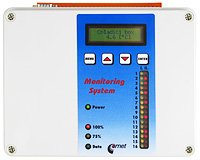
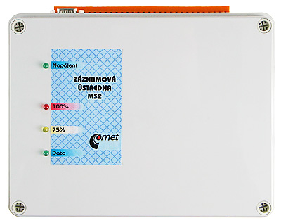
Monitoring system MS2+:
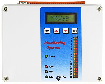
Monitoring system MS3+:
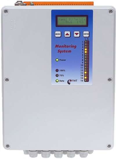
Monitoring and control system MS4+:
| STANDARD FEATURES OF AVAILABLE MODELS OF DATA ACQUISITION SYSTEM | MS2+ | MS3+ | MS4+ |
| record of data | YES | YES | YES |
| dual line LCD display and four buttons on the front panel | YES | YES | |
| alarm indication - audible and visible on the data logger panel | YES | YES | |
| output for external alarm indication | YES | YES | |
| built-in communication interface RS485, operation of several data loggers in the network | YES | YES | |
| 16 output relays | YES |
| DATA ACQUISITION SYSTEM TECHNICAL PARAMETERS | |
|---|---|
| Memory type: | internal SRAM, backed-up by Lithium battery |
| Total memory capacity: | 2MB (up to 480 000 values) |
| Data logging mode: |
noncyclic - logging stops after filling the memory cyclic - after filling memory oldest data is overwritten by new |
| Data logging interval: | adjustable individually for all input channels from 1 second to 24 hours |
| Real time clock: | year, leap year, month, day, hour, minute, second, backed-up by Lithium battery |
| Input measured values (1 to 16 inputs): | are defined for each channel by installed input modules (see table) accordingly to user requirements |
| Resolution of the AD converter (analog channels): | 16 bits, conversion duration approximately 100ms/channel |
| Interface for communication with computer: | RS232 (RxD,TxD,RTS,CTS,GND) - direct connection with computer up to 15 meters, connection with computer by telephone modem, GSM modem, USB converter, Ethernet converter |
| RS485 (only for MS3+, MS4+) - connection with computer up to 1200 m, possibility of connection of several data loggers to one communication link | |
| Supported communication speeds: | 1200, 9600, 19200, 57600, 115200 Bd |
| Output for alarm indication (only MS3+, MS4+): | voltage signal 0V/4.8V, maximum current 50mA, output is designed for connection of external audio indication or telephone dialer |
| Relay alarm outputs (only MS4+): | 16 relays (max. 8A/250Vac), switching-over contacts |
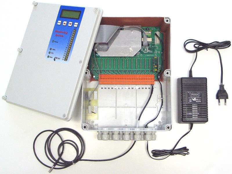
| Power: | from external ac/dc adapter, included in delivery (supplying from source 24V DC possible) |
| Operating temperature range of datalogger: | 0 to 50°C |
| Dimensions, weight - MS2+, MS3+: | 230 x 180 x 90 mm (W x L x D), weight approximately 800g |
| Dimensions, weight MS4+ (MS2+,MS3+ for thermocouple): | 250 x 320 x 110 mm (W x L x D), weight approximately 2000g |
| Protection: | IP20, optional watertight case IP55 (only MS2+, MS3+) |
| Warranty: | two years |
| TYPES OF INPUTS | ||||
|---|---|---|---|---|
| Type | Measured value | Accuracy | Note | |
| A0 | dc current 4 to 20 mA | ±0.1% FS | With source approximately 21V for two-wire transducers with current loop (e.g. temperature and humidity transducers Comet). Only galvanic not isolated. | |
| A1* | dc current 4 to 20 mA | ±0.1% FS | for passive sensing of current | |
| B0* | dc current 0 to 20mA | ±0.1% FS | ||
| B1* | dc current 0 to 1A | ±0.1% FS | ||
| B2* | dc current 0 to 5A | ±0.1% FS | ||
| C0 | ac current 0 to 20mA | ±1% FS | galvanic isolated | |
| C1 | ac current 0 to 1A | ±1% FS | galvanic isolated | |
| C2 | ac current 0 to 5A | ±1% FS | galvanic isolated | |
| D0* | dc voltage 0 to 100mV | ±0.1% FS | ||
| D1* | dc voltage 0 to 1V | ±0.1% FS | ||
| D2* | dc voltage 0 to 10V | ±0.1% FS | ||
| D3* | dc voltage 0 to 400V | ±0.1% FS | ||
| E0 | ac voltage 0 to 100mV | ±1% FS | galvanic isolated | |
| E1 | ac voltage 0 to 1V | ±1% FS | galvanic isolated | |
| E2 | ac voltage 0 to 10V | ±1% FS | galvanic isolated | |
| E3 | ac voltage 0 to 400V | ±1% FS | galvanic isolated | |
| F* | measurement of resistance (specify the range) | ±0.1% FS | two-wire connection | |
| J* | input for Nickel RTD temperature sensor Ni1000, 6180 ppm/°C, range -50 to +250°C | -50 to 100°C ±0.2°C 100 to 250°C ±0.2% from reading | ||
| K* | input for Platinum RTD temperature sensor Pt100, range -140 to +600°C | -140 to+100°C ±0.2°C 100 to 600°C ±0.2% from reading | two-wire connection | |
| K1* | input for Platinum RTD temperature sensor Pt1000, range -140 to +600°C | -140 to+100°C ±0.2°C 100 to 600°C ±0.2% from reading | two-wire connection | |
| N* | thermocouple K (NiCr-Ni) range -70 to +1300°C | ±(0.3% + 1°C) from reading | linearized, cold junction compensation | |
| T* | thermocouple T (Cu-CuNi) range -200 to +400°C | ±(0.3% + 1°C) from reading | linearized, cold junction compensation | |
| O* | thermocouple J (Fe-Co) range -200 to 750°C | ±(0.3% + 1°C) from reading | linearized, cold junction compensation | |
| P* | thermocouple S (Pt10%Rh-Pt), range 0 to 1700°C | ±(0.3% + 1°C) from reading from +200 to +1700°C | linearized, cold junction compensation | |
| Q* | thermocouple B (Pt30%Rh-Pt), range +100 to +1800°C | ±(0.3% + 1°C) from reading from +300 to +1800°C | linearized | |
| S* | binary input for potential-less contacts | maximum resistance of closed contact: 1000 ohms minimum duration for recording: 200ms |
| S1 | binary voltage input | voltage for "switched ON" state: 3 to 30Vdc, input current in the"switched ON" state: 1 to 9mA-depending on the applied voltage, minimum duration for indication of change: 200ms, galvanic isolated |
| CTU | counter input for voltage signal | voltage for "HIGH" state (for counter status change): 3 to 24Vdc maximum pulse frequency 5kHz, backed-up operation, galvanic isolated |
| CTK | counter input for potential-less contacts and open collector | maximum pulse frequency 5kHz, programmable filter of pulse ringing, backed-up operation during power mains failure, maximum resistance of closed contact: 10 kohms minimum resistance of open contact: 250 kohms, galvanic unisolated |
| FU | input for measurement of frequency of voltage signal | 0 to 5kHz, resolution 1Hz, accuracy ±(0.2% from reading + 1Hz) input voltage for state "H": 3 to 24Vdc input current in state "H": approximately 7mA minimum duration of input impuls: 30us, galvanic isolated |
| FK | input for measurement of frequency of contact switching | 0 to 5kHz, resolution 1Hz, accuracy ±(0.2% from reading + 1Hz) maximum resistance of closed contact: 10 kohms minimum resistance of open contact: 250 kohms, minimum duration of input pulse: 30us, galvanic unisolated |
| RS | input for serial signal RS485 for devices supporting Advantech protocol | e.g. measurement from transmitters with RS485 digital output connected to the serial RS485 network - ADAM Advantech protocol , galvanic isolated |
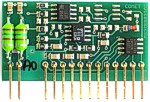
Input module A0 4 to 20mA
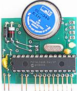
Counter input module CTU
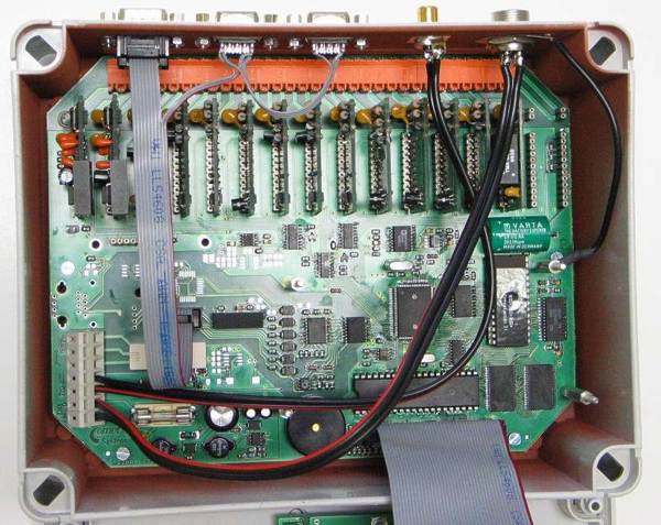
Opened MS3+ with 14 installed input modules
Notes: Inputs marked ( * ) are not galvanic isolated and have common ground. These inputs are available also as galvanic isolated. Galvanic isolated analog inputs are marked with letter G following the name of input type (e.g. input for passive measurement of current 4-20mA - type A1 - with galvanic isolation is marked A1G). Galvanic isolation is not designed as safety protection. Datalogger for thermocouple measurement has always larger case. Input RS always maps all channels from its position to position 16. Therefore input RS should always be installed to the position with the highest input channel number.
Included accessories:
Calibration certificate from the manufacturer - Comet, ac/dc adapter, wall holders, communication cable for RS232 of 2 meters length, free program for Windows. Free program is available to dowload anytime. Program enables to control all logger functions and view and print the record in numerical format.
| OPTIONAL ACCESSORY | ||
|---|---|---|
|
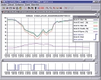
SWR006 | optional software for Windows - comfort graphic environment data acquisition, including on-line graph |
|
Watertight unit in larger case with cable glands with protection rate IP55 - only for MS2+, MS3+.
Not available for loggers with thermocouple inputs and MS4+.
Case dimensions 250 x 320 x 110 mm. |
|
| M2007 |
built-in interface for communication with the PC via Ethernet network - only for new MS3+, MS4+ |
|
| M2006 |
built-in interface for communication with the PC via USB port - only for new MS3+, MS4+ |
|
|
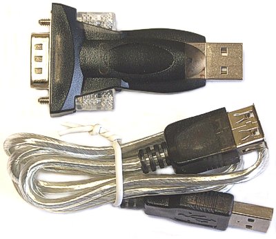
MP006 | external RS232/USB converter for communication with the PC via USB port |
| MP010 |
built-in independent interface for sending and reception of SMS - in case data logger is connected to the PC another way than via GSM modem - only for new MS3+, MS4+ |
|
|
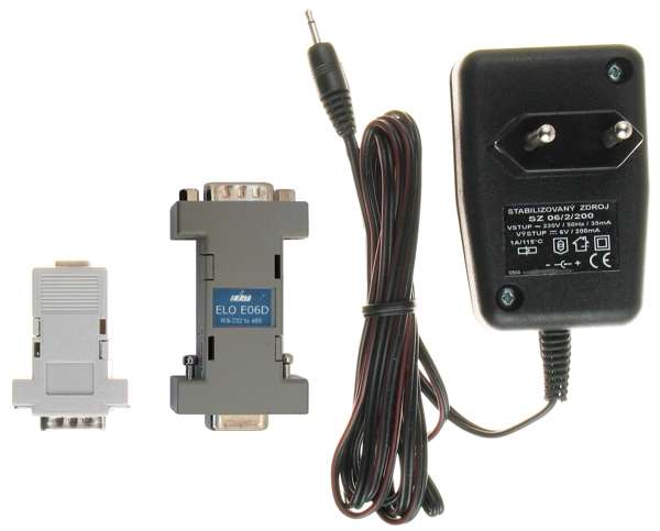
MP001 |
external RS485/RS232 converter for serial port COMx of the PC, ac/dc adapter
included - only for MS3+, MS4+ |
|
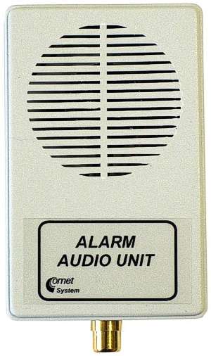
M2002 |
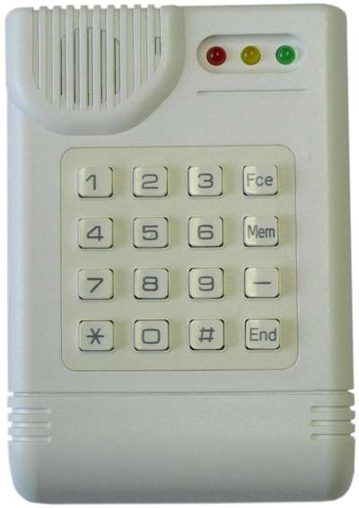
external audio indication unit - only for MS3+, MS4+ |
|
MP002 |
telephone voice dialer for alarm reporting, ac/dc adapter included - only for MS3+, MS4+ |
|
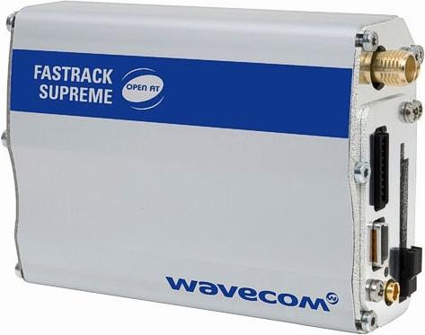
MP009 | GSM modem WaveCom Fastrack M1306B, without accessories |
| MP009/1 | antenna for GSM modem WaveCom Fastrack, right-angled |
| MP009/2 | communication cable for GSM modem Fastrack | |
| MP009/3 | ac/dc adapter 230V/12V for GSM modem Fastrack | |

|
humidity transmitters | humidity and temperature transmitters with 4-20mA output |

|
temperature transmitters | programmable temperature transducers with 4-20mA output |

|
temperature transmitters | temperature transducers with 4-20mA output |

|
humidity transmitters | humidity and temperature transmitters with serial RS485 output |

|
temperature transmitters | temperature transmitters with serial RS485 output |
 
|
probes | temperature probes with Pt1000/3850ppm sensor without connector - probe marking is followed by symbol /0 |
![]() Data sheet of MS2+,
MS3+, MS4+ data acquisition system in pdf format
Data sheet of MS2+,
MS3+, MS4+ data acquisition system in pdf format
![]() Basic part of the Instruction Manual for MS2+,
MS3+, MS4+ data acquisition system in pdf format
Basic part of the Instruction Manual for MS2+,
MS3+, MS4+ data acquisition system in pdf format
![]() Appendixes to basic part of the Instruction Manual for MS2+, MS3+, MS4+ data acquisition system in pdf format
Appendixes to basic part of the Instruction Manual for MS2+, MS3+, MS4+ data acquisition system in pdf format